Monday, November 23, 2009

Rudder Stock

Here is a description of how I went about making the rudder stock. To allow for the carpet on the inside of the case I started with packing tape on the board. Then I laid double sided tape over this.
I made a template & then cutout 3 layers of 1mm clear PVC. This was then double sided taped to the board. The last layer was a layer of thin mylar film.


I laid up the initial layers of carbon...4 layers at once is real messy!!!! I was not able to get a good vacuum so opted for just straight lay up. It was not as good as I would have hoped for but it all looked good.


Just a note to the ones who have not done this yet....make sure you mark the stock as top & bottom...otherwise you may just shape the bottom to the top profile. Luckily I left it a bit on the high side so I can still get a good shape....oops!!!

Also made a paper template for the spacer & glued that to the G10 tube. That is all for the moment. More to come.


Monday, June 29, 2009

Dagger Board Rudder Update

I have just started working on the rudder. My main concern was making sure that i got a profile that was true. When you have a high performance boat minor irregularities will tend to create problems at speed.
With that in mind i did a bit of research & found a person in Melbourne that can cut foam with a hot wire CNC cutter.
I gave him the dxf files that Ian gave me & here is the result.
The cutter was not able to shape the tip area but that can be done by hand. Overall i am very pleased with the result.
I think i will get him to do the dagger board as well. My attempts at shaping have left a little bit to be desired.

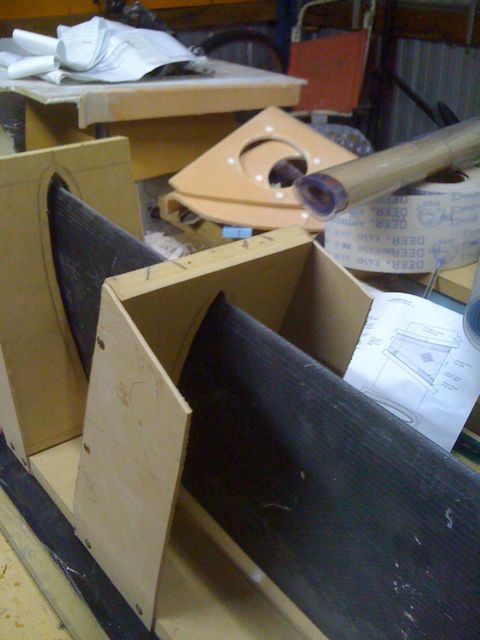
After much deliberation I decided that the best way to make the rudder was in 2 halves. By using the outer jacket as a mold & slicing the foil sections in half I can make the 2 halves & join them together.
The process that I have used is to mount the outer halves on 2 pieces of 25mm MDF board. I used a spray on contact adhesive for this


Once i had all 7 pieces down the next task was to create a mold for the tip. I did this by covering the foil section in tape & then making a mix of light auto body filler & then pushing the shaped tip section into the bog mix. After it had gone off I removed the tip section & cleaned up the filler.


Next step was to place a sheet of thin mylar film in the mold. I used the spray adhesive for this. I then taped the sides up with clear packing tape lapped over the edge of the mylar film to stop the epoxy from sticking to the foam. Next step was about 5 layers of mold release wax so that it will come out of the mold. I am hoping to make a 2nd spare rudder, just in case.


For the laminations I will only put the 1st layer of DB into the mold. The others will be placed over the complete blade once it is joined & removed from the mold. After the 1st DB layer I will then place the required layers of Uni followed by the other layers of DB for centre core support.
This then is vac bagged. Once done I started to fill in the rest of the internal parts with the shaped foil sections. I had to sand the shaped faces to allow for the laminates already laid down as I did not want to sand too much to get a flat half.
I also laid the balsa core. This was all laid in with a bog glue mix & then I used the vac bag to settle it into place.


This where I am up to at the moment. I am just about to start laying up the 2nd half today & then it will time to join them.

Interior Furniture 2

The Port side has taken a bit longer to formulate. The main reason was the question of how to do the galley.
Now I have finally decided & here is the result. I am not going to draw water from a tank. I will carry containers & dispense as required. The sink will have an outlet through the hull. I have kept the unit away from the opening under the cockpit seat so that I can use that area as a pantry. For storage I will also use the area under the stove as well as the existing hatch under the sink.
Just to the left of the unit I will incorporate a storage area for plates & cups


Sunday, May 31, 2009

Interior Furniture 1

The starboard side is well on the way but I am still mulling over how to do the galley on the port side.
The starboard side will contain the electrics. This will include VHF, Stereo, mainswitch etc. I have also decided to instal a false bulkhead to form a cupboard to hide the wiring on the rear of the hatch. This will also hide the back of the depth & speed instruments. I do not like seeing loose wiring so I will try & hide as much in conduits inside cupboards. The false bulkhead means that the position for the cicuit breaker switches will need to be changed. Ah the joys of foam & balsa...just patch it up.


The cupboard doors will be hinged at the top. This will, hopefully, mean that I can do without catches but I am not sure. I think they may be needed just to keep things inside.


The hinges are my own composite style & should be fine.

Monday, April 13, 2009

Bow wing


The bow wing has been glassed in. I used an old carbon fibre offcut from an A Class mast. I have shaped the cut outs taken from the hull sides to fit into the end of the section as an end stop. This also will serve as a good position for the nav lights. I have also decided to put a tang on the end to take the brace from the float end rather than fitting it to the hull side. I decided to clean up the glue while it was still a bit green so the glue area looks a bit furry. What the heck...it's cool down here & I am impatient!!!


This is just before filling with bog to allow fixing of the light as well as putting the wire inside the bow wing. By putting the wing so far forward i will be able to run my nets further forward just to be able to give me a bit more foredeck area. The sail track in the mast section will do just fine.

The profile of the nav light is a bit bigger than the wing section so i have made a backing plate from flat laminated glass


Next part of the bow wing will be to build 2 anchor storage/ fairleads in the middle of the wings. This will be great for cruising & enable me to run a bridle for anchoring. Of course i wont be having anchors stored there for racing.

Composite anchor cleats

This is the start of my composite anchor cleats. I am making them from flat carbon laminated to a thickness of about 5mm. I have heat formed the foam to the inner shape of the hull & then added a top piece of high density foam. Next step is to cover them in about 4 layers of carbon uni & 2 layers of BD 600. I will place 1 layer of BD600 followed by 4 staggered layers of uni the last layer will be BD600.
Once done they will then be laminated into the hull sides. These should be quite strong & I will not have to worry about through deck bolts & backing plates.


Sunday, February 22, 2009

Bow Tube

I was going to make a carbon fibre pole, but after much deliberation, I have decided to go with aluminium.
The problem being that with a bow tube of 95mm & a tube of 80mm OD, I needed to make a bush for the difference.I had some 100mm round waterpipe so I made a set of shims & used some of the blue PVC glue to glue them together. After a bit of adjusting i got a good fit & the pole slides in them.
With a bearing at the both ends of the tube the pole is a neat sliding fit.


This is the set up for retaining the bow pole. Instead of nuts I will get a couple of 12mm wing nuts.

Sunday, February 1, 2009

Bits & pieces

It was way too hot this week for any resin work, 3 days of 40 degrees C + weather. So what work that was done was prep work. One purchase that I made was a Dremel tool. It is fantastic for all those fiddly & hard to get to places. With a variety of bits it is great, although it is not designed for continuous use as it gets a bit warm.


I decided to add a bow wing but the big decision was where to fit it. I ended up fitting it just at the rear of the forestay bracket. This created another problem in that I would not be able to fit the pin for the bow pole. I solved this by bogging 2 12mm s/steel bolts either side of the bow tube. Once they are in place I will cove them in & wrap them in tape. I have some off cut of 10mm aluminium bar that will form a backing plate to hold the pole in place which will be held in place by 2 wing nuts.


I also made up some foam shapes to provide some shape to the CMM areas so that the water does not pool there.


I also cut out the holes for the rear cockpit hatches & did the initial fit to the rear mast support.


Thursday, January 1, 2009

Carbon Fibre Gooseneck

Time to start on the carbon fibre gooseneck. I had an off cut of mast section so this proved the ideal template. I wrapped it in plastic to stop the resin sticking to the aluminium. If you double click on this 1st image you will be able to read the lay up that I used. The 1st 2 layers of normal glass are to add as a protection so that the carbon fibre is not in direct contact with the aluminium.


Eveything went well & i wrapped the whole unit in clear packing wrap then vacuum bagged the whole unit.

The ridge from the sail track that can be seen here is good as a locator for the gooseneck on the mast.


Next job was to locate the pivot assembly. I used a 12mm diameter rod to align through the bush in line with the mast track. I cut a piece of 9mm foam as a spacer, then bogged the whole lot in place. Next job is to cover it with some more layers of carbon fibre.